A Raspberry Pi based camera. Hardware includes a Raspberry Pi A+, a camera module, various parts from Adafruit, and an old waterproof camera housing.
A collection of timelapses created with the camera can be found on YouTube.
SOFTWARE
The software is available on GitHub.
CONNECTING
Once the software has been installed and the server is running, connect to the camera via wifi. The default network SSID is picamera. Once connected to the camera, open a browser and navigate to:
http://192.168.42.1:8080/This connects to the server app running on the camera. From here, you can setup and run timelapses. Use the tab icons at the top to switch between the 3 main screens.
NOTE: the actual IP address of the camera depends on how the access point software was setup.
TIMELAPSE SETUP
This screen provides basic timelapse setup and execution.
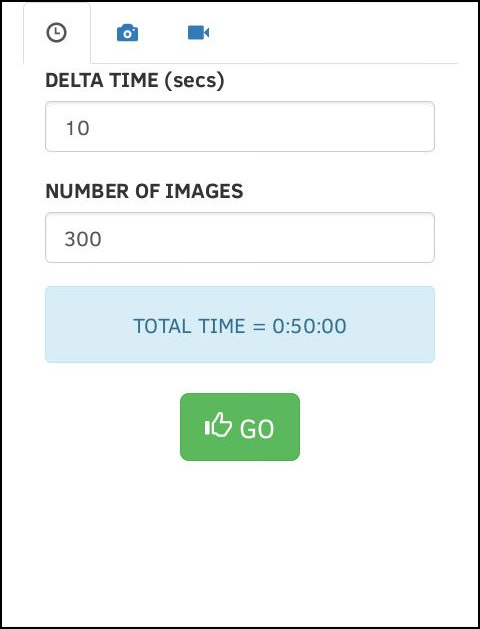
DELTA TIME sets the amout of time, in seconds, between each image acquisition. NUMBER OF IMAGES sets the total number of images that will be aquired. The resulting TOTAL TIME is shown in the blue box for the current setup.
To start the timelapse, press the [GO] button.
CAMERA SETUP
This screen provides basic camera setup and confirmation.
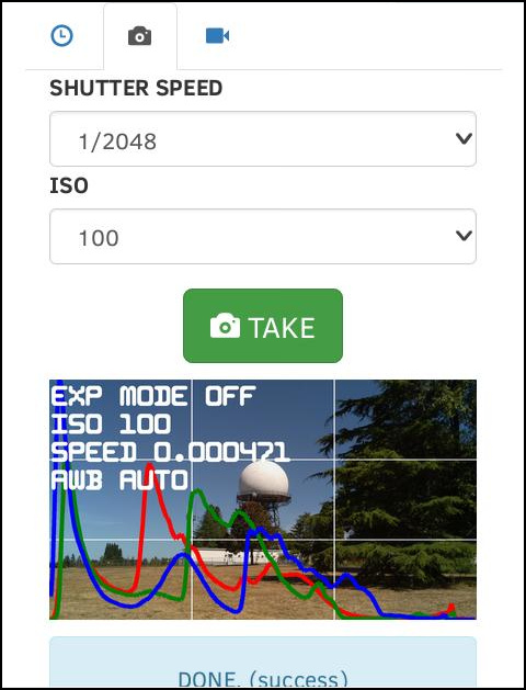
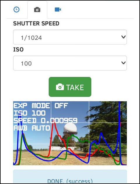
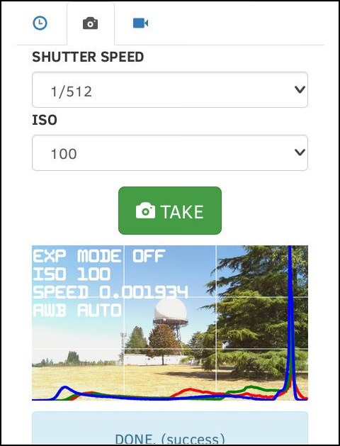
SHUTTER SPEED sets the desired shutter speed. ISO sets the desired sensitivity. To take a sample image with the current settings, press the [TAKE] button. Various information is overlayed on this preview image.
The RGB histogram provides a good indication for overall image exposure. In general, these curves should be centered as much as possible. In the above 3 examples, S=2048 is OK, but maybe a little too dark. S=1/512 is obviously too bright. With S=1/1024 the curves are centered better, so this is probably the best choice.
LIVE VIEW
This screen provides a live view image of the camera, useful for aiming
and aligning.
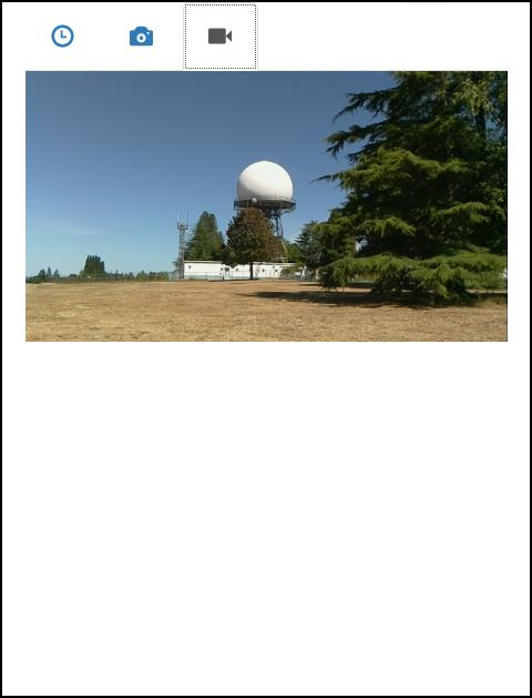
The live view is started and stopped automatically, so simply navigate to this tab to see the live view.
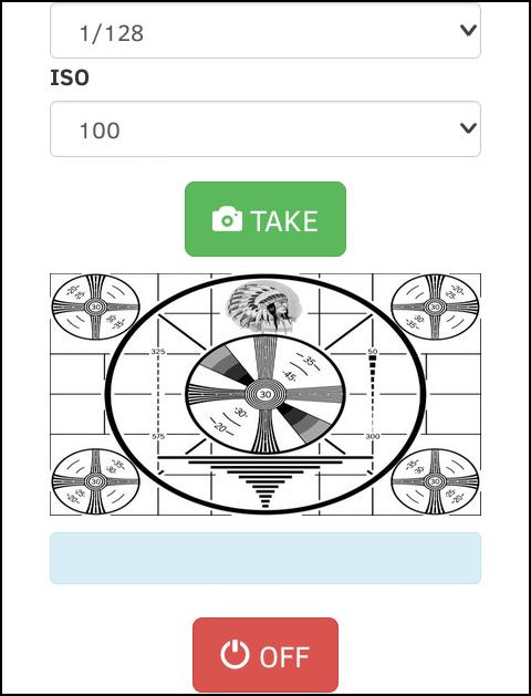
SHUT DOWN
In order to power down the camera safely, a shutdown command needs to
be sent to the system. To do this, simple navigate to the
CAMERA SETUP tab, scroll to the button, and find
the [OFF] button.
HARDWARE
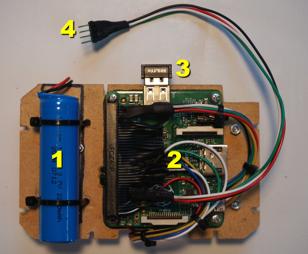
Here is a list of the main hardware components used.
- Raspberry Pi Model A+
- Raspberry Pi Camera Module v1
- Adafruit USB wifi dongle
- Adafruit Nokia LCD display
- Adafruit PowerBoost 500 Charger
- Adafruit 2200mAh lion battery
- Adafruit 5 way navigation switch
- Canon WP-DC20 Waterproof Case
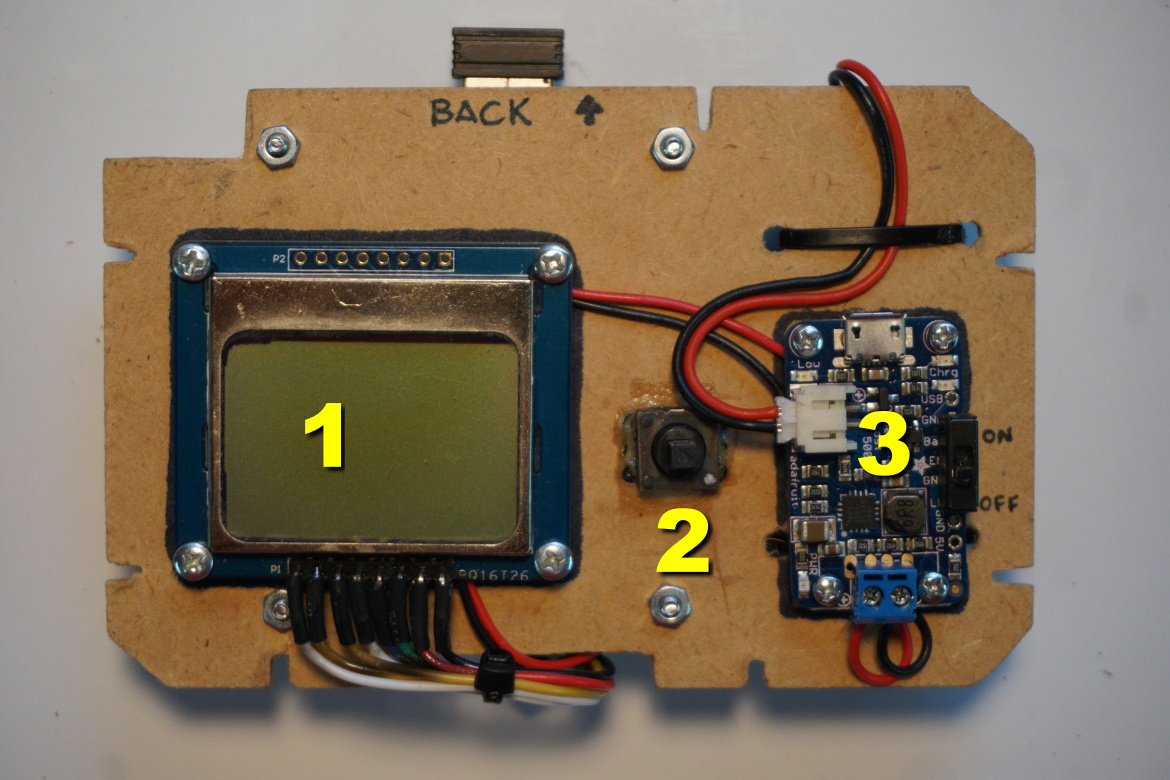
The front view of the main board is shown below (the camera module has
been disconnected). A ribbon cable is used to provide a low profile
connection to the GPIO header.
A drawing showing the wiring interconnect is provided in the
repo under the
doc folder.

Particle board was also used to create a simple friction fit mounting
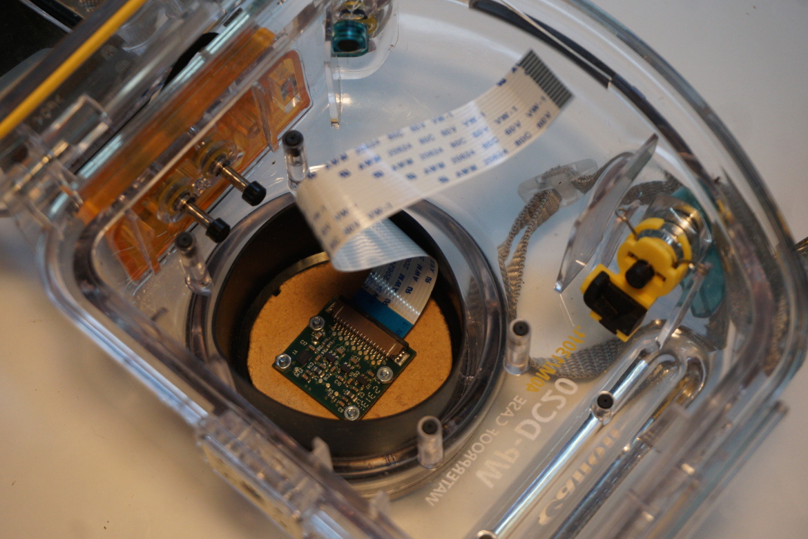
adapter for the camera module.
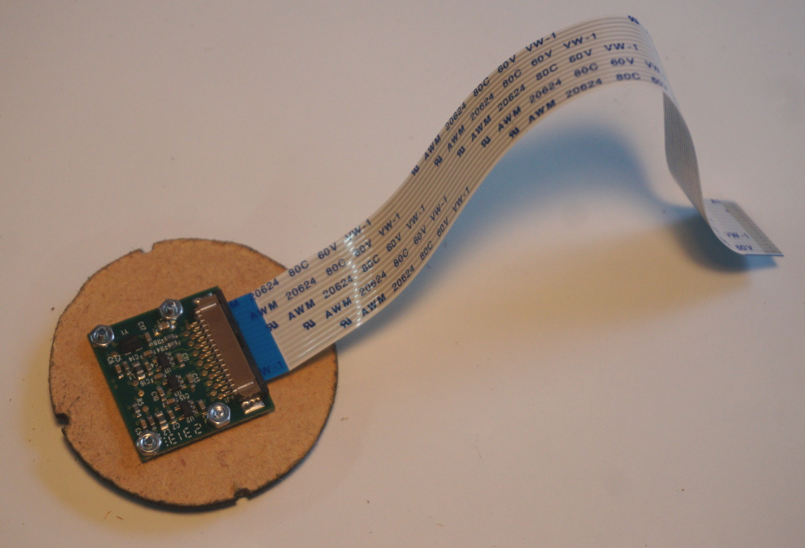
This mounting adapter fits into the bottom of the lens area.
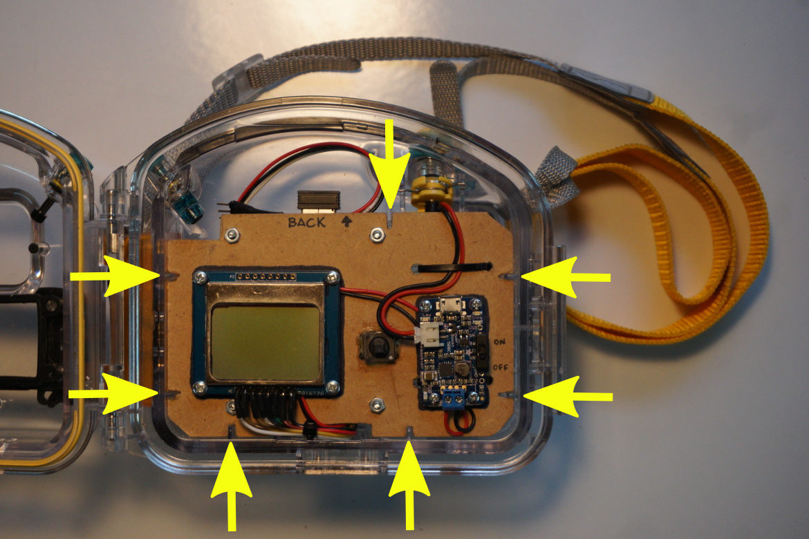
With the camera module installed, it is connect to the Raspberry Pi
on the main board and the whole thing is then installed as shown
below. There are several internal ribs that are used to hold the main
board in place.
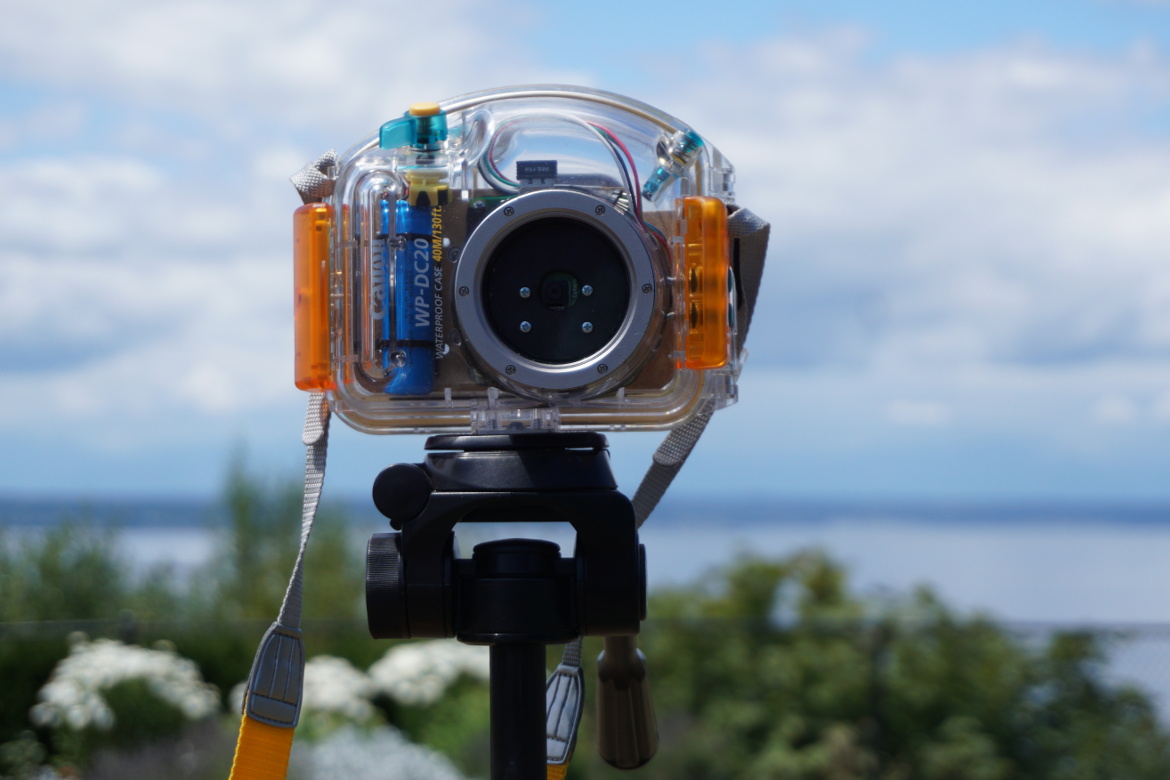
And here is the final product out in the wild.