LED Light Bulb Teardown
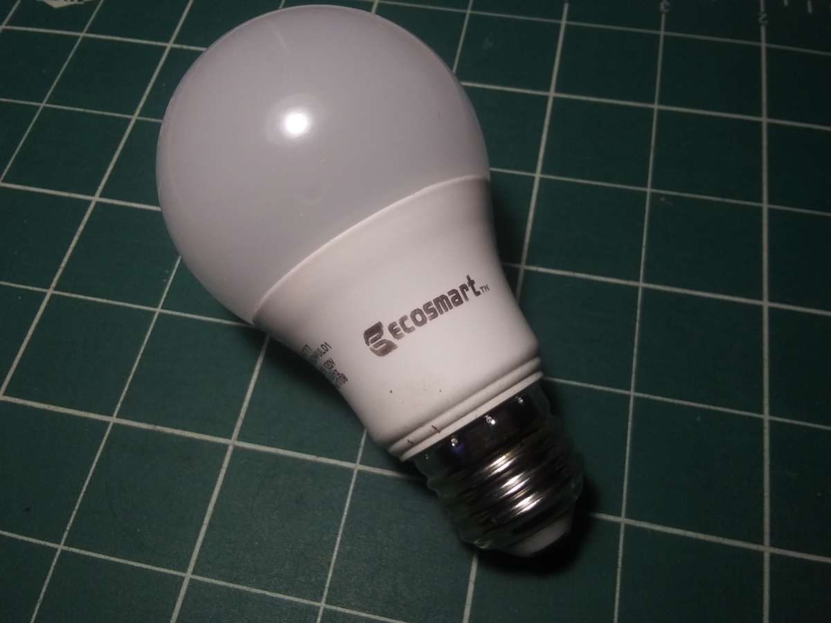
The LED Light Bulb
This LED light bulb stopped working. Let’s tear it apart and see what’s inside.
Metal Base Removal
Some prying and tearing and the metal base came off.
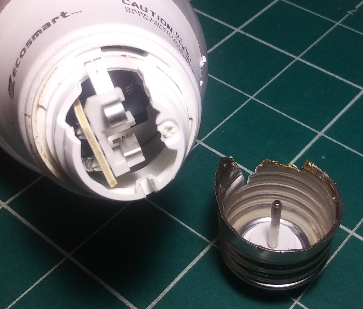
That central post mated with a spring loaded tang on the light bulb side. Another spring loaded metal tang made contact with the outer thread. This brought mains power in to the circuit board assembly.
LED Assembly Removal
More prying. This was sort a of snap fit with caulk adhesive deal.
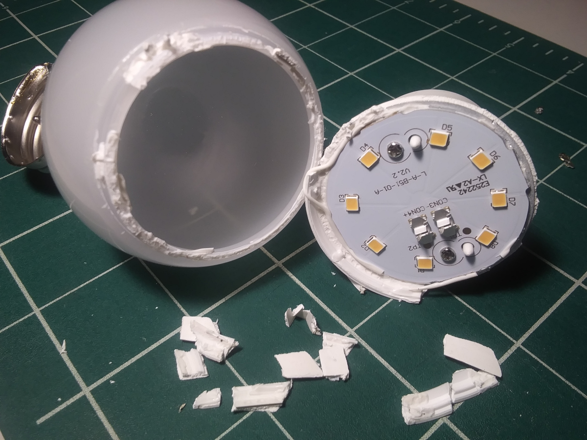
The whole upper portion is just an empty shell. It provides some diffusion, but more importantly provides the expected classic light bulb shape.
Here’s a closer top down view of the LED array. Two posts for alignment and two screws to hold it down.
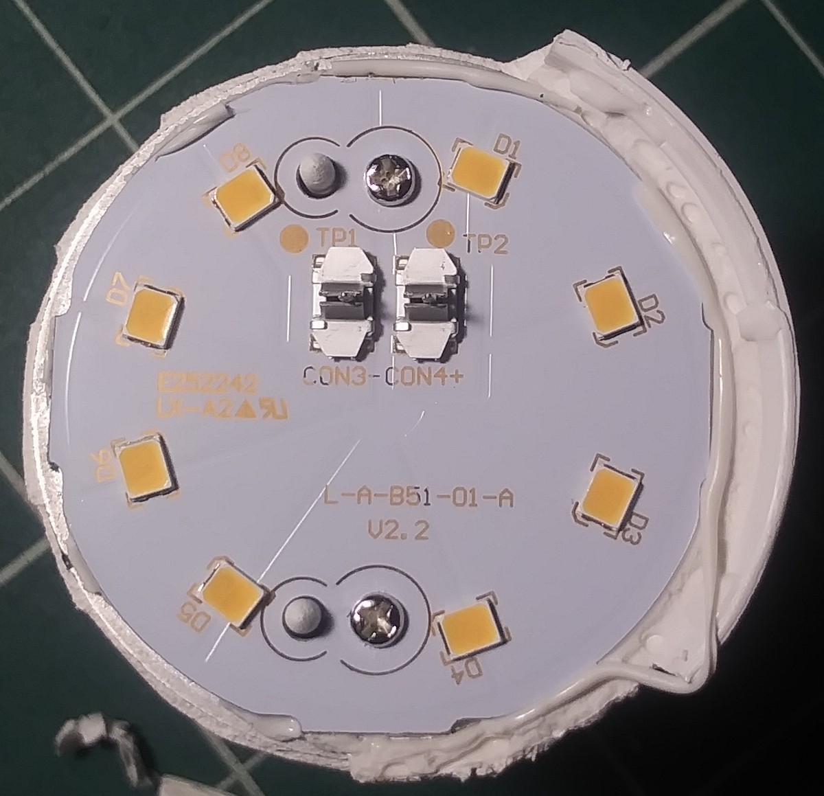
The LEDs appear to be connected in series, D1 to D8. The power comes in via
those two pins that slide through some spring like clamps into CON3- and CON4+.
Driver circuit
Removing those screws and the whole assembly slides out from the bulb. Here’s the driver circuit and LED assy next to each other.
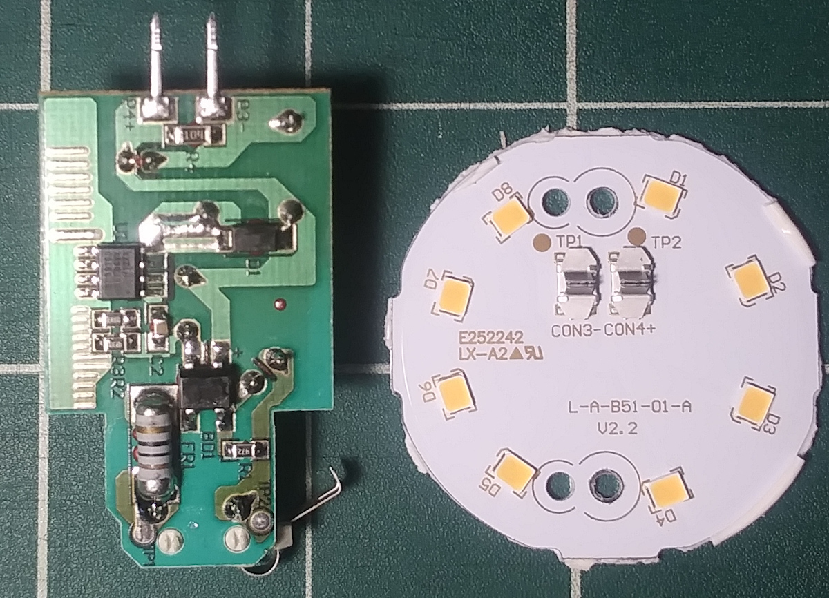
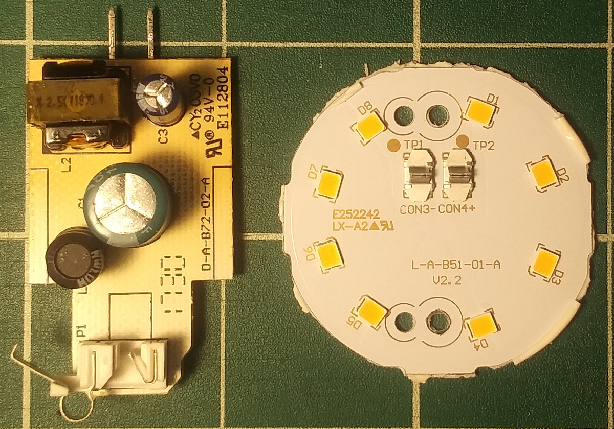
Main power comes in from the bottom. The two pins at the top are power output to the LEDs. Here’s the other side of the circuit board.
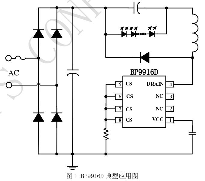
Reading the silk on the IC’s, the main one is an LED driver chip BD9916D.
The datasheet provides the following circuit.
Post mortem
Why did it die? Not sure. Nothing obvious. Probably something on the PCB. Might be fun to probe this later and see if the LEDs can be direct powered. But this was just a simple tear down documentation.
cheers!